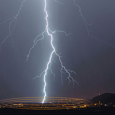
Equipotential bonding for photovoltaic systems
The physical distance of a PV system to the external lightning protection system should be maintained as much as possible, in order to protect it. If this is not possible due to local circumstances, then the necessary distance may be undershot, if
- the system is included in the external lightning protection system, meaning
- an insulated system is being created, e.g. with the high-voltage-resistant, insulated isCon® conductor.
Do you have any questions on this topic?
We’ll be glad to help
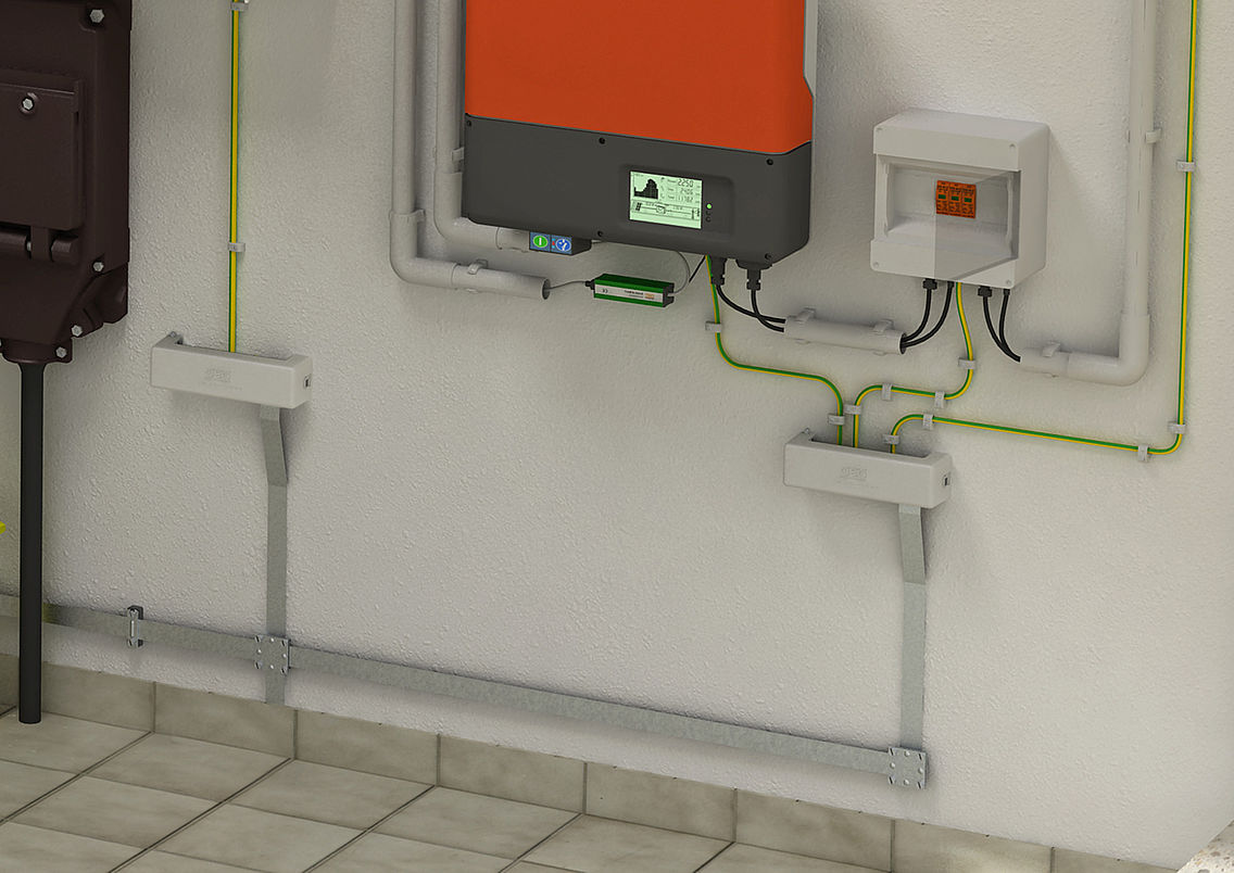
Important measures
The following points must be taken into account to guarantee comprehensive protection of the PV system:
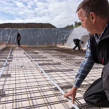
- Local earthing (PAS) must be connected to the main equipotential bonding (HPAS).
- Equipotential bonding cables must be routed close to, and parallel with, the DC cables.
- Data cables must be included in the protection concept.
Four steps to the comprehensive protection of photovoltaic systems
- Step 1: Check the separation distance
If the required separation distance cannot be ensured, then the metallic parts must be interconnected to be able to carry lightning current. - Step 2: Check the protection measures
Example: Measures for lightning protection equipotential bonding are used on the DC and AC side, e.g. lightning current arrester (type).
- Step 3: Include data cables
Data cables must be included in the protection concept. - Step 4: Provide equipotential bonding
Local equipotential bonding must be provided on the inverter.
Quick start
If the separation distance cannot be maintained
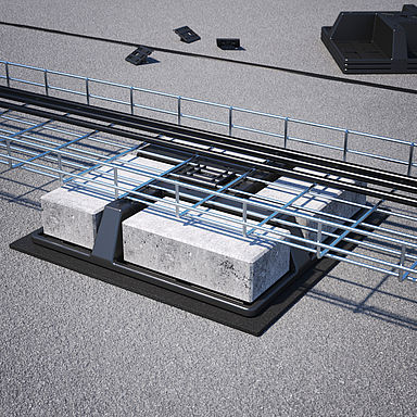
If the separation distance according to VDE 0185-305-3 (IEC/EN 62305-3) cannot be maintained for construction reasons, then the PV system must be connected to the lightning protection system using tested components with 16 mm2 CU or 25 mm2 aluminium. Lightning protection components for connection must be tested according to VDE 0185-561-1 (IEC/ EN 62561-1). In these cases, surge protective devices of type 1 (Class I) or combination arresters of type 1+2 (Class I+II) are required on the DC side, as lightning currents cannot be controlled in the building.
The necessary lightning protection equipotential bonding achieved in this way connects all the metallic and electrically conductive components of the system, including the earthing system, with the standardised lightning protection system. According to VDE 0185-305 Parts 3 and 4 (IEC/ EN 62305-3, -4), surge protective devices of (SPDs) type 1 (Class I) or combination arresters of type 1+2 (Class I+II) are to be used on cables running into the building. This applies both on roofs and on the ground, and for the AC and the DC side of the PV power supply system.
Of importance for the question regarding the necessity of surge protection measures are DIN VDE 0100-443 (VDE 0100-443) and DIN VDE 0100-712 (VDE 0100-712).
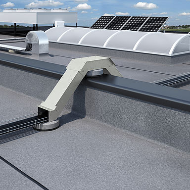
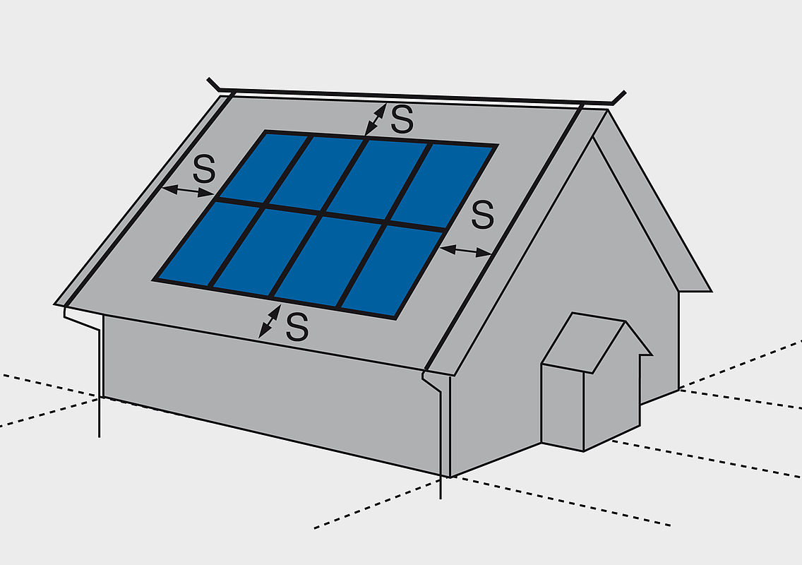
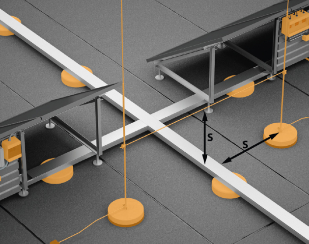
Separation distance for photovoltaic systems
According to DIN EN 62305, the lightning protection system must be erected at a separation distance (s) from the parts of the photovoltaic system. Usually, a separation distance (s) = safety distance of 0.5 m to 1 m is sufficient.
Air-conditioning systems, electrical sensors and photovoltaic systems are examples for roof structures in which the separation distance must be maintained. This distance is required to avoid dangerous sparking and partial lightning currents between both the external lightning protection system and the metallic building parts and electrical devices. In particular, when PV systems are refitted, this is often not possible due to the construction situation. The safe solution: The high-voltage-resistant, insulated isCon® system from OBO. With the isCon® conductor, a separation distance of 0.75 m through the air and 1.5 m for solid matter can be maintained safely.
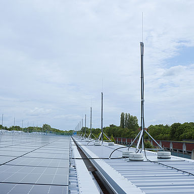
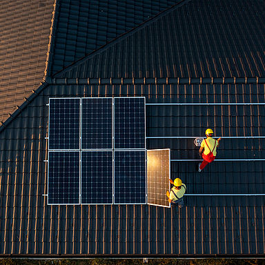
Position of the air-termination rods
The air-termination rods are to be positioned in such a way that there is no shading of the photovoltaic modules. A core shadow is sufficient to incur reductions in performance for the entire string. According to VDE 0185-305-3, Supplementary Sheet 5, an air-termination rod must be located at least 108x the diameter of the module away. In doing this, care should be taken that the photovoltaic system remains in the protection area of the air-termination rods. With the high-voltage-resistant, insulated isCon® system from OBO, the separation distance can be maintained safely.